Talking to the Battery: BMS Communication, Connectors and Safe Fast Charging for Light EVs

In January 2026 the London Fire Brigade reported that its firefighters had attended 206 e-bike and e-scooter fires across London during 2025 — an average of 17 a month, and a record. Around 83 percent of those incidents involved an e-bike: 171 fires.1 The Brigade used the figures to call for regulation.
Buried in the Brigade's own safety guidance is a sentence that ought to interest anyone who builds or buys charging hardware. Using the wrong charger, it warns, can overload a battery and raise the risk of overheating and fire; an incompatible charger can deliver the wrong amount of power to a pack, causing it to overheat, become damaged, or fail unexpectedly.2 In its incident notices the Brigade puts it more bluntly still: mismatching the charger increases the risk of fire.3
That is a statement about a relationship, not about a product. The battery is not a passive bucket that a charger fills. It is a managed system with its own controller — a battery management system, or BMS — that knows things the charger cannot see: cell temperatures, individual cell voltages, state of charge, and the limits beyond which the chemistry becomes unsafe. A charger that pushes current without asking is guessing. A charger that asks, listens, and adjusts is not.
This article is about that conversation: what the charger and the BMS actually exchange, why fast charging a light electric vehicle makes the exchange harder than it is for a car, what a real integration project requires from both sides, and how connectors and protection layers fit around it. It is deliberately a technical piece. If you are specifying charging hardware for two- and three-wheelers, these are the questions that separate a supplier who has done the work from one who has not.
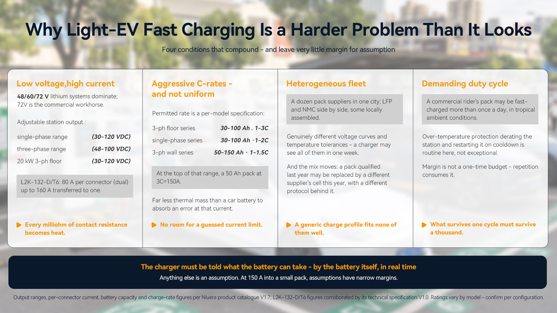
Why light EVs make this harder, not easier
There is an intuition that charging a motorcycle must be a simpler problem than charging a car, because the battery is smaller. The opposite is closer to the truth in several respects.
The voltage is low and the current is high. Light electric vehicles in the markets that matter — Southeast Asia, Africa, India, Latin America — run on 48 V, 60 V and 72 V lithium systems, with 72 V the workhorse for commercial riders. Niuera's DC stations cover that range directly: the single-phase range outputs an adjustable 30–120 VDC, and the three-phase range 48–100 VDC (with the 20 kW three-phase floor model at 30–120 VDC).4 Now do the arithmetic that a car engineer rarely has to: to deliver meaningful power at 72 V, you need a lot of amps. The L2K-132-D/T6, a 13.2 kW three-phase floor-standing unit, is rated 80 A per connector on the dual-connector configuration, with up to 160 A transferable to a single connector.45 High current at low voltage means every milliohm of contact resistance, every marginal crimp, every degraded connector pin turns into heat exactly where you least want it.
The C-rates are aggressive — and they are not uniform across the range. These packs are small, and operators want them full fast. The permitted rate is a per-model specification: the three-phase floor-standing series is rated for 30–100 Ah lithium packs at 1–3C, the single-phase series for 30–100 Ah at 1–2C, and the three-phase wall-mounted series for 50–150 Ah at 1–1.5C.4 At the top of that range a pack can be asked to accept current up to three times its capacity figure: a 50 Ah pack at 3C is 150 A. Compared with a car battery, a light-EV pack offers very little thermal mass to absorb a mistake at that current — which is the first reason the charger needs to be told the limit rather than assume it.
The fleet is heterogeneous and the chemistry varies. A car charger talks to a handful of vehicle platforms built by manufacturers with deep engineering resources. A light-EV charger in Nairobi or Hanoi may see packs from a dozen suppliers, some of them locally assembled, with LFP and NMC chemistries side by side. Those chemistries have genuinely different voltage curves and temperature tolerances.
And the duty cycle is demanding. A commercial rider's pack may be fast-charged more than once a day, in tropical ambient conditions. Whatever margin exists gets consumed by repetition.
Put those four together and the conclusion is not that light-EV fast charging is easy. It is that light-EV fast charging is a case where the charger must be told what the battery can take, by the battery itself, in real time. Anything else is an assumption, and assumptions at 150 A into a small pack are how the London figures happen.
What the handshake actually does
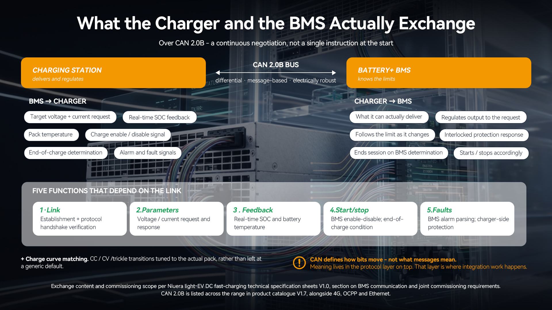
Niuera's DC fast-charging stations for light EVs carry CAN 2.0B communication for exactly this purpose, specified to communicate with the vehicle's battery BMS; it is listed across the range alongside 4G, OCPP and Ethernet.45 CAN — Controller Area Network — is the same robust, differential, message-based bus that has run automotive electronics for decades. It is a sensible choice here precisely because it is electrically tough and well understood.
What travels across it, in a properly integrated system, falls into five groups.6
1 — Link establishment and protocol handshake. Before any power flows, the two controllers have to agree that they are talking to each other and that they speak the same dialect. This is not a formality. CAN defines how bits move; it does not define what the messages mean. Message meaning is defined by the protocol layered on top, and that layer is where integration work lives.
2 — Charging parameter exchange. The BMS requests a target voltage and current; the charger responds with what it can actually deliver, and regulates to it. This is a continuous negotiation, not a single instruction at the start. As the pack fills and warms, the permitted current changes, and the charger follows.
3 — Real-time feedback: state of charge and battery temperature. The BMS reports SOC and pack temperature back to the charger. This is what allows the charger to behave differently at 20 percent and at 90 percent, and differently at 25 °C and at 50 °C.
4 — Start/stop logic. The BMS provides an explicit charge-enable or charge-disable signal, and the two sides agree the conditions that end a session. "The battery is full" is a determination the BMS makes, not something the charger infers from a timer.
5 — Abnormal state handling. The BMS raises alarm and fault signals; the charger parses them and responds with an interlocked protection action on its own side. A cell-level problem that only the BMS can see becomes a charger-level shutdown.
There is a sixth item that is less a message than a design outcome: charge curve matching. The charging strategy — the transitions between constant-current, constant-voltage and trickle stages — gets tuned to the actual battery's characteristics rather than left at a generic default.6
Notice what this list implies. Every one of these functions depends on the charger understanding the specific BMS it is connected to. Which brings us to the part of the process that most charging-hardware suppliers do not talk about publicly.
The unglamorous part: what a co-debug project actually requires
Niuera's technical specification sheets for the DC fast-charging range include a dedicated section on BMS communication and joint commissioning. It sets out, in plain terms, what the customer must supply before an integration can be considered done.6 We reproduce the substance of it here because it is a fair description of what this work costs — on both sides.
What the customer provides:
-
The battery BMS charging CAN protocol document — covering CAN ID definitions, message format, communication baud rate, data frame structure, and the charging control logic. Not a summary; the actual definitions.
-
A battery sample — at least one complete pack with its BMS, for laboratory communication co-debugging and charge-function verification. At least one, physically, in a lab.
-
The battery's basic parameters — rated voltage, rated capacity in Ah, maximum and minimum charging voltage, maximum charging current, recommended C-rate, and operating temperature range.
What the joint commissioning then covers:
-
CAN link establishment and protocol handshake verification
-
Charging parameter interaction: voltage and current request/response, real-time SOC feedback, battery temperature monitoring
-
Start/stop logic: the BMS charge enable/disable signal, and end-of-charge condition determination
-
Abnormal state handling: parsing BMS alarm and fault signals, and the charger-side interlocked protection response
-
Charge curve matching: optimising the strategy to the battery's characteristics across constant-current, constant-voltage and trickle stages
Three things are worth drawing out of that list.
First, it is honest about needing hardware. You cannot integrate a BMS from a PDF. Protocol documents contain errors, omissions and undocumented behaviours; the only way to find them is to put a real pack on a real charger in a lab and watch what happens. Any supplier who tells you integration is a firmware parameter change has not done it.
Second, it puts an obligation on the buyer. If you are a fleet operator or a vehicle OEM specifying chargers, your battery supplier has to be willing to hand over a CAN protocol document and a sample pack. That is a commercial conversation you may need to have before the charging conversation. It is a common reason integration projects stall, and it is better discovered at the quotation stage than after delivery.
Third, timing is explicit. The specification is direct on this point: if the customer has application-layer charging-protection requirements, these must be raised at project kickoff, so that engineers on both sides can agree a co-debug plan and fold it into the development schedule.6 Requirements that surface after the hardware is built are expensive requirements.
Two layers of protection, and why both are needed
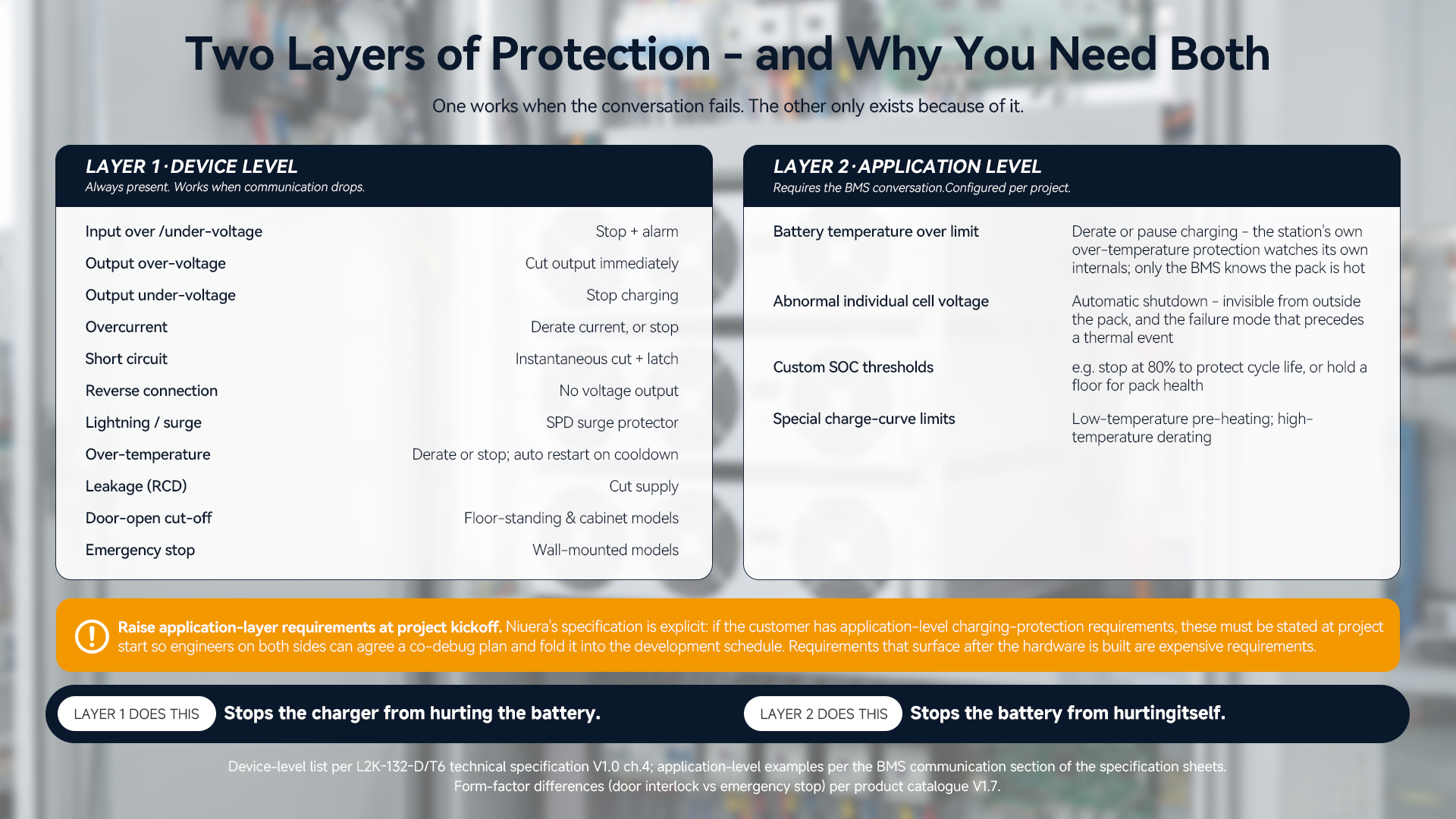
Protection in a well-built charging station is not one thing. It operates at two distinct levels, and conflating them is a common specification error.
Layer one: device-level protection, always present
The floor-standing cabinet models carry a standard set of protections that operate regardless of what the battery says — because they have to work even when communication has failed. On the L2K-132-D/T6, the specified set is:5
|
Protection
|
Behaviour
|
|
Input over/under-voltage
|
Station stops and alarms when input is out of range
|
|
Output over-voltage
|
Output cut immediately, protecting the vehicle battery
|
|
Output under-voltage
|
Charging stops when output falls below threshold
|
|
Overcurrent
|
Current automatically reduced, or station stops
|
|
Short circuit
|
Output cut instantaneously and latched
|
|
Reverse connection
|
No voltage output if connector polarity is reversed
|
|
Lightning / surge
|
SPD surge protector against strikes and grid transients
|
|
Over-temperature
|
Derate or stop; automatic restart once temperature normalises
|
|
Leakage (RCD)
|
Supply cut when residual current exceeds limit
|
|
Emergency stop
|
Front-panel button cuts all outputs immediately
|
|
Door-open cut-off
|
Output cut when the cabinet door is opened
|
One model-specific distinction matters here, and it is the kind of detail that gets flattened in marketing copy. The two form factors carry different last-resort protections, because they are physically different machines. The floor-standing and cabinet models list output cut-off when the door is opened — they have a serviceable door, and the interlock prevents live working. The wall-mounted models list the same core electrical protections but, having no cabinet door, list an emergency stop function instead.4 Ingress protection follows the same logic: IP55 on the floor-standing models, IP54 on the wall-mounted ones.4
For the L2K-132-D/T6 specifically, the specification sheet states an operating range of −20 °C to +55 °C with cold start down to −40 °C, and automatic restart once internal temperature returns to normal after an over-temperature event.5 Operating temperature is specified per model; confirm the figure for the configuration you are buying.
Layer two: application-level protection, via the BMS
The second layer is where the handshake earns its keep. Because the charger can see what the BMS reports, protections become possible that no amount of device-level hardware can provide. Niuera's specification gives examples of what can be implemented at this layer:6
-
Derate or pause charging when battery temperature exceeds a limit. The station has its own over-temperature protection, but that watches the station's internals. Only the BMS knows the pack is too hot.
-
Automatic shutdown on abnormal individual cell voltage. A single failing cell is invisible from outside the pack. It is also exactly the failure mode that precedes a thermal event.
-
Custom SOC protection thresholds. An operator may want sessions to stop at 80 percent to protect cycle life, or to hold a floor for battery health.
-
Special charge-curve limits — low-temperature pre-heating strategies, high-temperature derating.
The distinction is worth stating plainly, because it is the article's central point: device-level protection stops the charger from hurting the battery. Application-level protection stops the battery from hurting itself. The first is a hardware property. The second requires the conversation.
Connectors: the physical half of compatibility
Communication is one half of compatibility. The other half is the plug, and here light EVs have a genuine standard — though how it is applied is a project decision rather than a fixed given.
Niuera's DC fast-charging stations offer the Type 6 connector defined in IEC 62196-6:2022 as a selectable interface option across the range, rather than as a single fixed fitting.45 It is worth knowing what that standard actually covers. IEC 62196-6:2022, published in April 2022, applies to vehicle connectors, vehicle inlets and cable assemblies for electric vehicles in conductive charging systems that incorporate control means, at a rated operating voltage up to 120 V DC and a rated current up to 100 A.7 The Type 6 interface itself derives from the CHAdeMO Association's ePTW (Electric Powered Two-Wheeler) specification, which defined a DC charging method for that same voltage and current envelope.8
Two observations follow.
The phrase "which incorporate control means" is not decoration. The standard's scope assumes a charging system with a control channel — the communication this article is about. The connector and the conversation are two halves of one design, defined together.
The 120 V DC / 100 A envelope is where the Type 6 option sits — and current above it is a specification decision, not an assumption. Several configurations in the range are rated at or below that current: the L2K-132-D/T6 is rated 80 A per connector in dual-connector service, and the 20 kW three-phase model 100 A.4 Others are specified above it. The single-phase 7.2 kW models are rated 100 A at 72 V or 120 A at 60 V, with a 120 A maximum; and the L2K-132-D/T6's dynamic power allocation can transfer up to 160 A to a single connector.45
This is precisely why the interface is offered as an option rather than a fixed fitting — the platform is built to be configured to differing project requirements. Two practical consequences follow, and they are worth stating plainly because this is where loose specification causes trouble.
First, the interface and cable rating for a high-current configuration is a project-specific specification — something to fix in writing with the supplier for the duty you are actually buying, not something to infer from a connector type named on a datasheet. Second, because the rated current in IEC 62196-6:2022 is 100 A, a configuration operating above that figure should be specified and documented on its own terms, with an interface rated for the duty, rather than treated as covered by the base standard. Neither point is unique to Niuera; it applies to any light-EV platform quoting high single-connector currents. But it is the question a technically literate buyer should ask, and the answer belongs in the purchase specification rather than in a brochure.
Adapters are not an afterthought in these markets
A standard helps only where it has been adopted. Across Southeast Asia and Africa the installed vehicle base uses a variety of inlets, and no single connector dominates. Niuera's specification addresses this directly: the charging interface conforms to IEC 62196-6:2022, and for the differing LEV interface requirements of Southeast Asian and African markets, customised adapter solutions or OEM-specific interfaces can be provided.6 The catalogue notes compatibility with mainstream local connectors and adapters, including Type 2 and T-type plugs.4
For an operator, the practical implication is a procurement question rather than an engineering one: which vehicles will actually arrive at this station over the next five years, and does the hardware I am buying have a path to serve them? A station that fits one fleet's inlet and nothing else is a station with a strategic risk built into it.
Lithium only — and why the exclusion is a feature
Niuera's specification sheets carry a notice that deserves more attention than a caveat usually gets. The DC fast-charging products are designed for lithium battery (LFP / NMC) fast-charging applications and are not suitable for lead-acid fast charging; customers with lead-acid requirements are directed to contact the company for a specific solution.6
It would be easy to read that as a limitation. Read it instead as a design position. Lead-acid and lithium want fundamentally different treatment: different voltage curves, different tolerance for high current, different end-of-charge determination, and — critically — lead-acid packs in this vehicle class typically have no BMS to talk to at all. A charger built to negotiate with a lithium BMS and tuned to lithium charge curves is not a charger that should be quietly pointed at a lead-acid bank. A supplier who says so in writing is telling you they understand their own product's envelope.
In markets where lead-acid still holds a meaningful share of the two- and three-wheeler fleet, this matters commercially as well as technically: the answer to a mixed fleet is a deliberate specification decision, not an assumption that DC fast charging is universal.
What to ask a charging supplier
If you are evaluating light-EV DC charging hardware, the following questions separate suppliers who have done integration work from those who have not. They are drawn directly from the requirements set out above.
-
Does the station communicate with the battery BMS, over what bus, and at what protocol layer? "CAN" alone is an answer about wiring, not about meaning.
-
What exactly do you need from us to integrate our packs? A supplier who has done this will ask for a CAN protocol document, a physical sample pack, and the battery's electrical and thermal parameters. One who does not ask for a sample has not integrated.
-
What does joint commissioning cover, and who does it? Look for handshake verification, parameter interaction, start/stop logic, fault-signal handling and charge-curve matching as named deliverables.
-
Which protections are device-level and which are application-level? Both lists should exist and be distinct.
-
Can we specify application-layer protections — temperature derating, cell-voltage shutdown, SOC thresholds — and by when must we ask? The honest answer includes a deadline: at project kickoff.
-
What connector, to what standard, at what rated current per connector — and what is the cable rating for the configuration we are buying? Ask for the per-model figure, not the range-wide claim.
-
What is the adapter path for the vehicle inlets in our market?
What battery chemistries is this product designed for, and which are excluded?

The takeaway
The London Fire Brigade's warning about mismatched chargers is, in engineering terms, a warning about missing information. A charger that does not know the battery's temperature, its cell-level condition, its permitted current, or its own judgement of when it is full, is operating on assumptions — and in a low-voltage, high-current, high-C-rate, high-ambient-temperature application, assumptions have narrow margins.
The fix is not more protection hardware bolted on afterwards, though device-level protection remains essential and must work when communication fails. The fix is that the charger and the battery are designed to talk, and that somebody does the unglamorous laboratory work of making a specific charger talk to a specific pack: exchanging protocol documents, putting a real sample on a real machine, verifying the handshake, and matching the charge curve to the chemistry actually in front of them.
That work does not photograph well and it does not fit on a spec sheet line. It is, nonetheless, most of the difference between a charging station that is safe with your fleet's batteries and one that is merely safe in general.
Integrating with your battery platform
Niuera works with vehicle manufacturers, fleet operators and battery suppliers to commission DC fast charging against specific battery platforms — covering CAN protocol integration, laboratory co-debugging with sample packs, application-layer protection strategies, and connector or adapter configuration for the target market.
Send us your battery specification and BMS CAN protocol and our engineers will confirm the integration scope for your platform. Reach us at info@niuera.cn or +86 0512-68303879, or visit www.niueraenergy.com.
FAQ
Does the charger need to communicate with the BMS, or can it just supply current?
For safe fast charging of lithium light-EV packs, communication is what allows the charger to follow the battery's actual limits — permitted current and voltage, real-time SOC, pack temperature, and the BMS's own charge-enable and end-of-charge determination. Niuera's DC stations carry CAN 2.0B for communication with the battery BMS.456
What do we need to provide for an integration project?
The battery BMS charging CAN protocol document (CAN ID definitions, message format, baud rate, data frame structure, charging control logic), at least one battery pack sample with its BMS for laboratory co-debugging, and the battery's basic parameters — rated voltage, rated capacity, maximum and minimum charging voltage, maximum charging current, recommended C-rate and operating temperature range.6
Can we specify our own charging-protection rules?
Yes — application-layer protections such as temperature-based derating, shutdown on abnormal cell voltage, custom SOC thresholds and special charge-curve limits can be implemented through the BMS CAN link. These requirements should be raised at project kickoff so both engineering teams can agree a co-debug plan.6
What connector do the stations use?
Type 6, per IEC 62196-6:2022, is offered as a selectable interface option across the range — a standard applicable to conductive charging systems incorporating control means, at up to 120 V DC and up to 100 A rated current. Customised adapter solutions and OEM-specific interfaces are available for the differing LEV inlets used across Southeast Asian and African markets, with compatibility noted for mainstream adapters including Type 2 and T-type plugs.4567
What output current is available per connector?
It depends on the configuration. The L2K-132-D/T6 is rated 80 A per connector in dual-connector service, with dynamic power allocation able to transfer up to 160 A to a single connector; the 20 kW three-phase model is rated 100 A; the single-phase 7.2 kW models are rated 100 A at 72 V or 120 A at 60 V with a 120 A maximum.45 Confirm the interface and cable rating for your specific duty in the purchase specification — and note that any configuration operating above the 100 A rated current in IEC 62196-6:2022 should be specified on its own terms, with an interface rated for the duty, rather than assumed to fall under the base standard.7
What protections work if communication drops?
The device-level set operates independently of the battery link: input over/under-voltage, output over- and under-voltage, overcurrent, short circuit, reverse connection, lightning/surge, over-temperature and leakage (RCD). The last-resort protection differs by form factor — floor-standing and cabinet models list output cut-off when the door is opened, while wall-mounted models list an emergency stop function. The L2K-132-D/T6 specification sheet lists both an emergency stop button and door-open cut-off.45
Can these stations fast-charge lead-acid batteries?
No. The DC fast-charging products are designed for lithium (LFP / NMC) applications and are not suitable for lead-acid fast charging. Contact Niuera to discuss requirements involving lead-acid packs.6
Which battery voltages are supported?
Output is adjustable across 30–120 VDC on the single-phase range and 48–100 VDC on the three-phase range, with the 20 kW three-phase floor model at 30–120 VDC — covering the 48 V, 60 V and 72 V lithium systems common in light electric vehicles.4
Which battery capacities and charge rates are supported?
This varies by model and should be checked per configuration: the three-phase floor-standing series is specified for 30–100 Ah lithium packs at 1–3C, the single-phase series for 30–100 Ah at 1–2C, and the three-phase wall-mounted series for 50–150 Ah at 1–1.5C.4
References
-
London Fire Brigade — Record number of e-bike and e-scooter fires across London in 2025, as Brigade calls for regulation to be introduced (January 2026).
-
London Fire Brigade — Buying safe e-bikes, batteries and chargers and How to charge e-bikes and e-scooters safely, fire safety guidance.
-
London Fire Brigade — incident safety notices accompanying e-bike fire reports (2024–2026).
-
Suzhou Niuera Energy Co., Ltd. — Electric Motorcycle / Light Electric Vehicle Fast Charging Stations product catalogue, V1.7 (2026).
-
Suzhou Niuera Energy Co., Ltd. — L2K-132-D/T6 Technical Specification, V1.0 (May 2026).
-
Suzhou Niuera Energy Co., Ltd. — technical specification sheets for the light-EV DC fast-charging range, V1.0 (May 2026), section on BMS communication and joint commissioning requirements.
-
IEC 62196-6:2022 — Plugs, socket-outlets, vehicle connectors and vehicle inlets — Conductive charging of electric vehicles — Part 6: Dimensional compatibility requirements for DC pin and contact-tube vehicle couplers for DC EV supply equipment where protection relies on electrical separation, published April 2022; scope as summarised in the published standard abstract.
-
CHAdeMO Association ePTW (Electric Powered Two-Wheeler) DC charging specification, as the basis of the Type 6 interface.
Product specifications cited above are drawn from Niuera product catalogue V1.7 and technical specification sheets current at the time of writing, and are subject to change. Output current, battery capacity and charge-rate ratings vary by model; please confirm the specification for your configuration with Niuera for any specific project. Fire incident statistics are attributed to the London Fire Brigade and reflect that authority's published figures. Standard scopes are summarised from published abstracts; consult the full standard text for authoritative requirements.
One DC Bus, Three Energy Sources: Inside an Integrated Solar-Storage-Charging System for E2W/E3W Fleets
Solar, Storage, Charging: Why South America's E-Moto Infrastructure Should Be Built as One System
Related blog