Silicon Carbide in EV Charging Modules: What It Actually Changes — and What It Doesn't
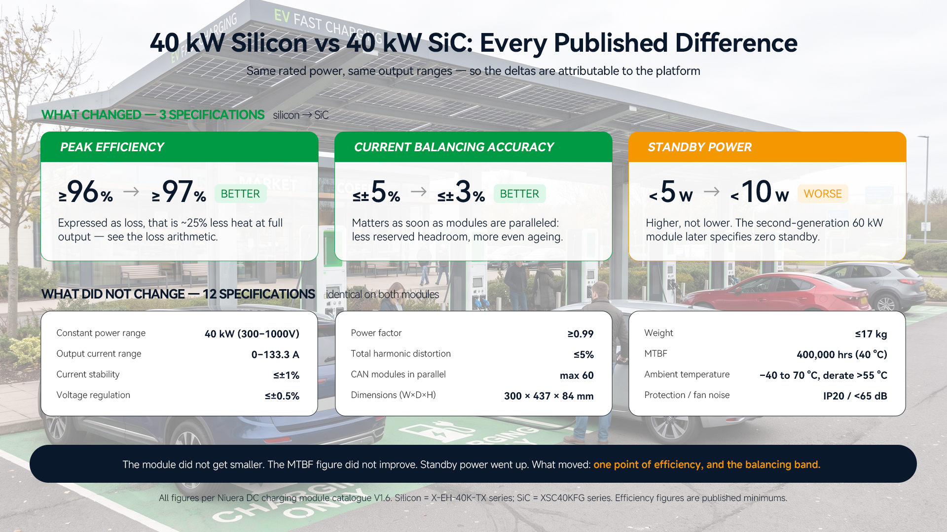
The like-for-like comparison
|
40 kW silicon (X-EH-40K-TX)
|
40 kW SiC (XSC40KFG)
|
|
|
Peak efficiency
|
≥96%
|
≥97%
|
|
Current balancing accuracy
|
≤±5%
|
≤±3%
|
|
Standby power
|
<5 W
|
<10 W
|
|
Constant power range
|
40 kW (300–1000 V)
|
40 kW (300–1000 V)
|
|
Output current range
|
0–133.3 A
|
0–133.3 A
|
|
Current stability accuracy
|
≤±1%
|
≤±1%
|
|
Voltage regulation accuracy
|
≤±0.5%
|
≤±0.5%
|
|
Power factor
|
≥0.99
|
≥0.99
|
|
Total harmonic distortion
|
≤5%
|
≤5%
|
|
CAN modules in parallel
|
max 60
|
max 60
|
|
Dimensions (W×D×H)
|
300 × 437 × 84 mm
|
300 × 437 × 84 mm
|
|
Weight
|
≤17 kg
|
≤17 kg
|
|
MTBF
|
400,000 hrs (40 °C)
|
400,000 hrs (40 °C)
|
|
Ambient temperature
|
−40 to 70 °C, derate above 55 °C
|
−40 to 70 °C, derate above 55 °C
|
|
Protection class
|
IP20
|
IP20
|
|
Fan noise
|
<65 dB at 1 m
|
<65 dB at 1 m
|
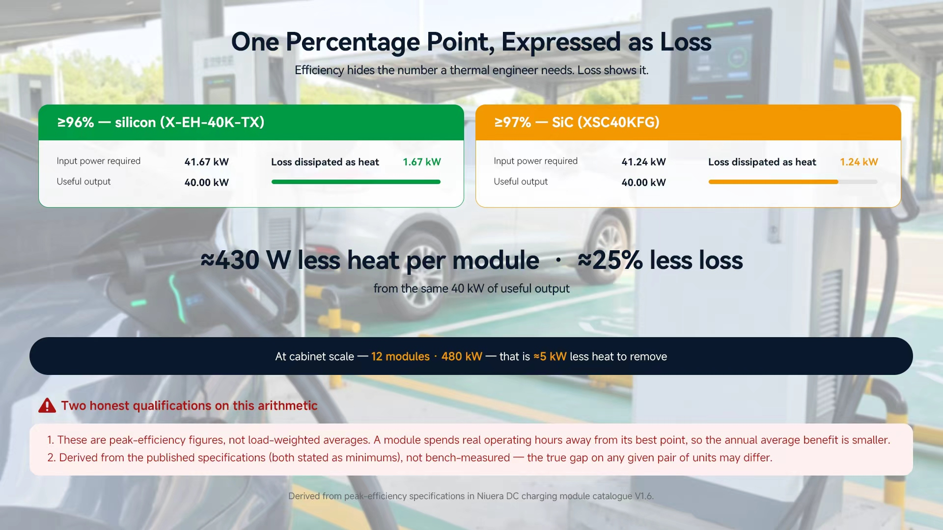
Why one percentage point is not a small number
|
40 kW at ≥96%
|
40 kW at ≥97%
|
|
|
Input power required
|
≈41.7 kW
|
≈41.2 kW
|
|
Loss dissipated as heat
|
≈1.67 kW
|
≈1.24 kW
|
The envelope stayed the same — and that is a design choice, not a missed opportunity
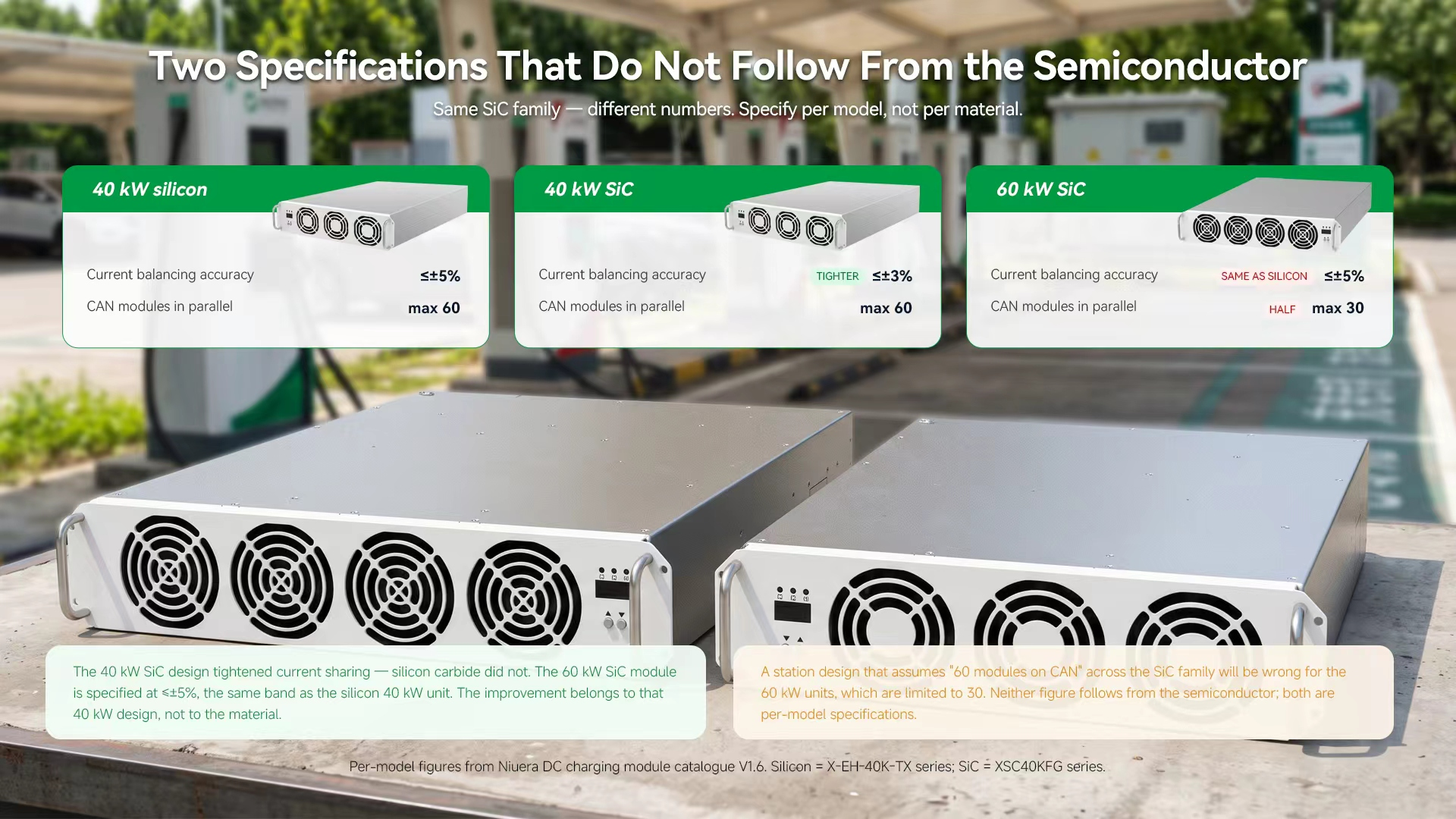
Current balancing: the improvement nobody puts on a banner
What SiC did enable: a higher power class in a single air-cooled module
The clearest contribution of silicon carbide in this range is not visible in the 40 kW comparison at all. It is visible in what exists above it.
The silicon AC-DC line tops out at 40 kW. The SiC line continues to 60 kW — in a single, still air-cooled module.3 That is the capability step: not a smaller 40 kW unit, but a 60 kW unit that remains a rack-mounted, air-cooled, hot-swappable module rather than escalating to liquid cooling.
The second-generation 60 kW module makes the packaging argument concrete. Comparing it with the 40 kW SiC module:3
|
40 kW SiC |
60 kW SiC (G2) |
|
|
Efficiency specification |
≥97% |
≥97% — held at 1.5× the power |
|
Dimensions |
300 × 437 × 84 mm |
300 × 437 × 126 mm |
|
Rack footprint (W×D) |
300 × 437 mm |
300 × 437 mm — identical |
|
Height |
84 mm |
126 mm (1.5×) |
|
Weight |
≤17 kg |
≤29 kg |
|
Output current range |
0–133.3 A |
0–200 A |
|
CAN modules in parallel |
max 60 |
max 30 |
|
Standby power |
<10 W |
zero standby power |
|
Fan noise |
<65 dB at 1 m |
<60 dB |
|
Communication |
CAN |
isolated CAN interface |
The topology is a hybrid, not a swap
What to ask when specifying modules
-
Is the efficiency figure peak or load-weighted? A peak number tells you the best point, not the duty cycle. Both figures here are peak.
-
What is the current balancing accuracy for this exact model? It varies within a range built on the same semiconductor — ±3% and ±5% both appear.
-
How many modules can be paralleled on this exact model? 60 and 30 both appear in the same SiC family.
-
What does the derating curve look like, not just the ambient range? Every module here is −40 to 70 °C with derating above 55 °C; the shape of the curve above 55 °C is what determines summer output.
-
What is standby power? It differs by generation, and in a large installation idle modules are a continuous cost.
-
What is the rack footprint, and does more power mean a new slot geometry or just more height?
-
Is MTBF quoted with a temperature? These are specified at 40 °C; a figure without a temperature is not comparable to one with it.
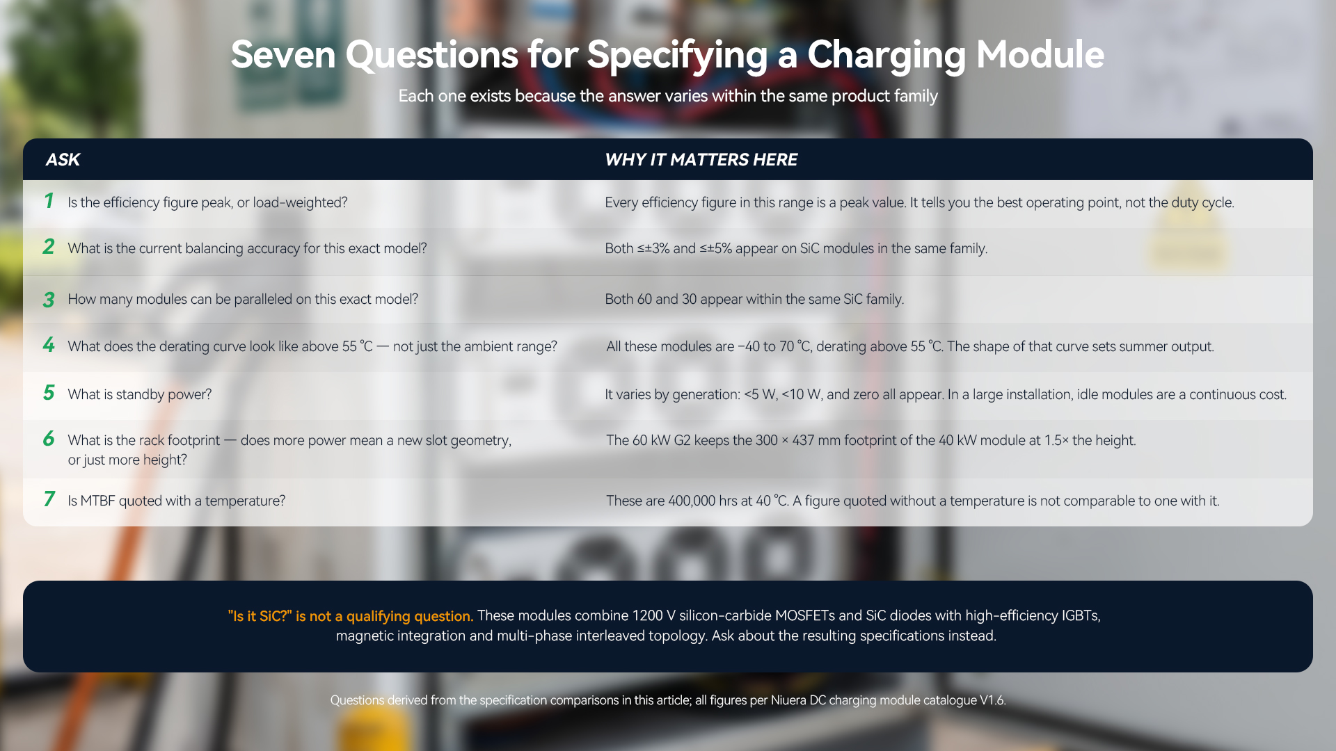 Figure 5. Seven questions for specifying a charging module
The takeaway
Getting the specifications
Full specifications for the 40 kW and 60 kW SiC AC-DC charging modules, and for the silicon modules they sit alongside, are available on request — including derating curves, output characteristic curves and protection parameters for each regional variant (China, US and EU input ranges).
Request the module specifications at info@niuera.cn or +86 0512-68303879, or visit www.niueraenergy.com.
──────────────────────────────────────────────
FAQ
How much more efficient is the SiC module than the silicon one?
At the same 40 kW rating, peak efficiency is specified at ≥97% for the SiC module and ≥96% for the silicon module. Expressed as loss, that is roughly 1.24 kW against 1.67 kW of heat at full output — about 25% less loss. Both figures are peak-efficiency specifications, not load-weighted averages.3
Is the SiC module smaller or lighter?
No. At 40 kW both modules are 300 × 437 × 84 mm and ≤17 kg. The efficiency gain was banked as thermal margin rather than spent on reducing the envelope.3
Does SiC improve the reliability figure?
Not in the published specification. Both the silicon and SiC modules are specified at 400,000 hours MTBF at 40 °C.3
Can I assume the same current balancing and paralleling limits across the SiC range?
No, and this is the most common specification error. The 40 kW SiC module is ≤±3% balancing with up to 60 modules on CAN; the 60 kW SiC module is ≤±5% with up to 30. These are per-model figures.3
What is the highest-power air-cooled module available?
60 kW. The silicon AC-DC line stops at 40 kW; the SiC line extends to 60 kW while remaining air-cooled and rack-mounted. The second-generation 60 kW module keeps the 300 × 437 mm rack footprint of the 40 kW unit at 1.5× the height, and holds the same ≥97% efficiency specification at 1.5× the power.3
Are these modules full SiC?
No — they combine 1200 V silicon-carbide MOSFETs and silicon-carbide diodes with high-efficiency IGBTs, magnetic integration and multi-phase interleaved parallel topology, under dual-core DSP control.3
What standby power should I budget for idle modules?
It depends on the generation: <5 W on the silicon 40 kW modules, <10 W on the 40 kW SiC module, and zero standby power on the second-generation 60 kW module.3
──────────────────────────────────────────────
References
- IET Power Electronics — A review of silicon carbide MOSFETs in electrified vehicles: application, challenges, and future development (2023).
- Energies — Comparative Dynamic Performance Evaluation of Si IGBTs and SiC MOSFETs (2025).
- Suzhou Niuera Energy Co., Ltd. — DC Charging Module Product Catalogue, V1.6 (2026). All module specifications cited in this article are taken from this document.
- PatSnap — SiC replacing IGBT in EV inverters patent-landscape analysis (2026), on hybrid and full-SiC architectures in traction applications.
- EV Engineering & Infrastructure — How 800 V architectures are challenging EV thermal management (2026), on rising local heat flux as footprints shrink.
Product specifications cited above are drawn from the Niuera DC charging module catalogue current at the time of writing and are subject to change; efficiency, current balancing, paralleling limits and standby power are per-model figures and should be confirmed for the specific model and regional variant in any project. Loss figures expressed in kilowatts are arithmetic derived from the published peak-efficiency specifications and are illustrative of the full-output operating point rather than a load-weighted average. Third-party research findings are attributed to the sources listed and describe their own test conditions, which differ from this product comparison.
One DC Bus, Three Energy Sources: Inside an Integrated Solar-Storage-Charging System for E2W/E3W Fleets